


In this video, you will learn
what a HART analog sensor is, how HART is used with analog sensors,
how a HART analog sensor works, and what advantages a HART analog
sensor can give your operation. Before we get into today’s
video, if you love our videos, be sure to click the like button below, and make sure to click subscribe and the bell to receive notifications
of new RealPars videos. This way you never miss another one! Current-loop technology has been used for
analog sensors for the past 4 decades to transmit important process
data to the control system, whether that system is a DCS
(distributed control system) a PLC (programmable logic controller),
or a single-loop controller. Current-loop data transmission
is simple and cost effective. Only a small amount of current
(4 to 20 milliamps to be exact) is required over a single pair of
wires for each current loop sensor. One 2-amp, 24 Volt DC power supply
can “drive” dozens of sensors. For current-loop analog sensors, the lowest measurable process value is
called the Lower Range Limit, or LRL.
The analog sensor will output 4
milliamps at this 0% reading. The highest measurable process value is
called the Upper Range Limit, or URL. The analog sensor will output 20
milliamps at this 100% reading. Many analog sensors, such as pressure and
temperature sensors, are inexpensive, and good quality sensors can be
purchased for US$100 – US$500. More complex flow, level, and
analytical sensors do cost more, but these still only require a single pair
of wires to allow the process variable, or measured variable, to be
transmitted to the control system. Another positive feature of
analog sensors and transmitters is that the signal can be carried a great distance along
a single pair of wires with little or no signal loss. A current signal can be
transmitted up to 1000 meters through 18-gauge wires with
no appreciable signal loss. Lastly, 4-20 milliamp current loop signals
provide a basic level of diagnostics. Since 0% equals a 4 milliamps signal, a broken wire would break the circuit
and 0 milliamps would be sensed. This “live zero” feature, where 0% is equal
to a value of greater than 0 milliamps, allows the control system to detect
a broken wire at 0 milliamps.
But analog sensors can only send one “value” over
a single pair of wires to the control system. And the granularity, or precision, of the data is
limited by the type of analog to digital converter (or A-to-D converter”) used by
the control system electronics. However, with modern electronics,
this is not as much of an issue. An A-to-D converter with 16-bit precision can report the
range of values for an analog sensor in 65,535 increments. This means that for a
0 – 1000 psi pressure sensor, the granularity of the signal value is
1000 divided by 65,535, or 0.015 psi. This level of precision would be
sufficient for most applications. Before we answer the
question of what HART is, let’s look quickly at another analog
device; the analog telephone. Analog telephone communication is similar to
analog sensor signals used in industrial plants.
Analog telephone lines transmit voice
as 48 Volt DC electrical signals. When you speak into the
handset of your phone, the microphone converts the sound
waves into analog electrical waves. These waves propagate over the
telephone line to their destination. The receiving phone then
converts the electrical signals back into sound waves through
the speaker of the handset. One pair of copper wires
for voice transmission, and one conversation
(or transmitted value) at a time. All just like an industrial analog sensor. In the late 1970’s, Bell Labs
invented the Bell 202 modem standard.
In 1980, the Bell 202 standard was
adopted as the communications standard for subsea oil and gas
production control systems. Bell 202 specifies a modulation method
known as audio frequency-shift keying (AFSK) to encode and transfer digital
data at a rate of 1200 bits per second, half-duplex (meaning, transmission
only in one direction at a time). Basically, it provides a continuous
signal, as an AC sine wave, that shifts its frequency from 1200
Hertz, indicating a binary value of 1, to 2200 Hertz to indicate a binary value of 0. Here’s the kicker. If we superimpose a Bell 202 signal on top
of a standard analog telephone line signal, we gain the ability to send digital data AND analog
data at the same time on the same pair of wires. This was used to transmit the caller’s
telephone number along with the voice call. This feature is well-known as Caller ID. So what if we superimposed
a Bell 202 signal on top of a standard
analog sensor line signal? We gain the ability to send
digital data AND analog data at the same time on the
same pair of wires.
This is HART communication! With
HART, we can send analog data, the measured value of the process variable,
along with digitally-transmitted data, such as a tagname, or calibration
settings, or sensor diagnostics. This would be a real productivity
enhancement for the process plant! And because HART-enabled sensors require only
a single pair of wires for communication, to upgrade an existing non-HART
sensor loop to a HART-enabled loop, no wiring changes are required! Of course, both the sensor
and the analog input card at the controller would
need to support HART.
The good news is that HART is built-in to
most commercially-available analog sensors and HART-enabled analog input cards are available
from nearly all DCS and PLC manufacturers. There are even add-on hardware devices to convert
your HART sensors into wireless transmitters! Now that we know what HART is, let’s
finish the discussion of how HART works. First, HART is an acronym for “Highway
Addressable Remote Transducer”. This simply means that a small network can
be formed with up to 63 HART devices, each having its own
address, or node number. Because a sensor can be
remotely accessed using HART, the name really does say it all: “highway (or
network) sensor (also called a transducer) that has an address so that it can
be accessed remotely and directly”.

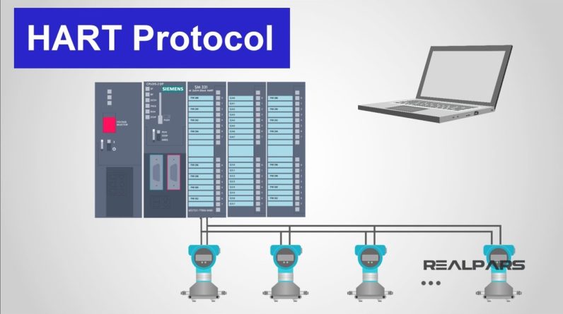
The remote capability of HART sensors
is very useful and powerful. In this diagram, we see a HART sensor
connected to a PLC analog input card. We can access data in the sensor remotely
using the HART communication protocol from the PLC programming software. That means we do not have to be at the
location of the sensor to access its data. We can configure, calibrate,
and retrieve diagnostic data from a control room or other location
where the HART data is accessible.
Data from a HART sensor must be
requested by the master node, which controls all conversations on the loop. The master node is typically the DCS or PLC
analog input card that the sensor is wired to. Each message from the master
includes the request type, such as “send measurement value”, the node number of the sensor
the message is intended for, and any data that needs to be
transmitted to the sensor, like a new value for the upper range limit. By using a hand-held programming
and configuration device, often called a “HART communicator”, the sensor data can be accessed
wherever the opportunity exists to connect the hand-held device
in parallel to the loop wires. This can be in a junction box, marshaling
panel, or at the sensor itself. So if a sensor is in an
inaccessible or hazardous area, configuration or maintenance of the sensor
can be done from a safe, remote location. Networking HART devices, in most control
systems applications, is not practiced. Because of its limited speed and its
cumbersome multi-drop network topology, we generally assign only one node,
or sensor, to each HART signal loop.
Fortunately, HART allows
for multiple master nodes, so that the control system AND a hand-held
communicator can both be connected to the loop and can communicate with the
device at the same time. With HART, the analog 4-20 milliamp
signal AND the digital HART protocol are both available to the control
system and instrument technician. If a sensor loop is upgraded from
‘analog only’ to ‘analog plus HART’, the control system programming and configuration
for the measurement value can stay the same. You can imagine that
superimposing an AC signal on top of a DC signal might interfere
with the 4-20 milliamp signal. But this is not the case. The AC HART sine wave
oscillates at either 1200 Hertz for a 1 value or at 2200 Hertz for a 0 value. The amplitude of the AC sine wave remains
the same, and for every oscillation, the amplitude of the first half of each
sine wave above the DC current curve exactly equals the amplitude of the second
half of each sine wave below the DC current.
The net effect of the sine wave is then zero. So the analog value of the sensor measurement
data is not affected by the HART signal, just as a telephone voice conversation
is not effected by the caller ID signal using the same Bell 202 protocol. Every HART device is capable of sending and
receiving 35-50 different information items, including the process variable (that is, the same measurement value as
provided by the 4-20 milliamp analog signal); device status; diagnostic alerts,
like “sensor value under range”; basic configuration parameters,
like upper and lower range limits; and the tagname of the device.
HART is a perfect choice for
multivariable instruments, like mass flow meters, where
mass flow, volumetric flow, temperature and density can all be communicated
to the control system over a single cable. The HART protocol is governed by a
vendor-independent association, The HART Communication Foundation, so HART sensors from any manufacturer can be
interchanged with those of other manufactures. This makes implementation, maintenance,
and troubleshooting very easy. Also, HART is used extensively
for final control devices, such as control valve positioners, with the same benefits and
diagnostic capabilities. Even though the HART standard
requires manufactures to provide a minimum number of specific
data items with every HART sensor, vendors can also extend the data set
to include vendor-specific items, like sensor model numbers or firmware
versions or advanced diagnostic counters. In order for the control system to recognize
the type and values for these custom data, a special description file, called a
Data Description (DD) file is required. This file is loaded on the DCS or PLC
configuration station or downloaded to the hand-held communicator and becomes
directly associated to the sensor. This file simply allow the data stream
from the sensor to be correctly parsed, or interpreted, and allow the technician or engineer
to make the correct requests for sensor data.
To review, HART is a digital
data communication protocol that is layered on top of a traditional
analog 4 – 20 milliamp signal which provides advanced data
retrieval and configuration options to be executed remotely from a DCS or PLC
system or from a hand-held communicator. HART communicates over a
single pair of wires, so adding HART to an existing 4 – 20 milliamp
sensor loop requires no wiring modification. Only the hardware at the analog input card and the sensor electronics may need to be
upgraded so that HART functionality is provided. A high percentage of sensors already installed in
4 – 20 milliamp loops are already HART-enabled. HART may be the fieldbus you
already have in your plant. Through simple configuration,
a wealth of new process data and diagnostic capability can be obtained
with a minimum of effort and expense. Make sure that you Head
on over to realpars.com. To find even more training material for
all of your PLC programming needs. We offer you many videos to assist
you in learning PLC programing and landing that job in high-paying, highly thought after field of
automation and controls engineering.
Go to realpars.com and subscribe to our
highly effective training series now..